Date posted: August 13, 2009
– Download EXTREME Core Upgrade on the E-Flight Blade CX3 as PDF –
We look at the EXTREME core upgrade for your E-Flight CX line, from parts to installation. Sick of breaking blades? Try some new ones that fold, they prove to be much more durable!
Please, be careful with this one… It’s…
EXTREME
Over the last ten years, we’ve seen ‘extreme’ become the new ‘fantastic’ or ‘amazing’. You don’t just buy and drink Mountain Dew, you experience it to the EXTREME. Doritos? I only let these chompers bite through the EXTREME Doritos. In fact, we’ll be launching the EXTREME HOVER AND SMILE site as soon as I can figure out which month of the year is the most EXTREME. When I do, I’ll post a link. Not just any link, but an EXTREME link.
I distinctly remember back in college watching three commercials back to back, all for different products, all marketing to the EXTREME.
Case in point…Remember the 80s commercials for ALL Detergent? The little kid spells out A-L-L by pointing to each letter as mommy washes the tablecloth said kid decided to play ‘paint-by-number-with-marinara-sauce’ upon not two seconds before. That’s not extreme enough, however. I imagine EXTREME ALL to be a bit more simple, but oh so much more EXTREME.
So, now that I have you in the proper EXTREME mindset, let’s examine the EXTREME Core Upgrade available for the Blade CX line. Available from www.flyrcrivesud.com, the extreme core completely replaces both shafts of the CX, CX2, or CX3 line. Not extreme enough for you? Okay, then, it replaces your blades as well, adding the ‘folding’ blade mounts seen on other helicopters. The kit promotes less blade clashes (honestly I’ve never had one on my CX3, but okay….), and higher durability in the blades. Now that I’m interested in, as I’ve destroyed my fair share of CX blades.
The site boasts a few promotions now and then, and I decided to pick up a couple for the price of one just for the sake of taking my CX3 apart again and trying something new. If your stock CX3 flies fine, and you don’t break blades, and you don’t clack them together like Ma ringing the dinner bell, then you don’t really need this upgrade. However, it gives me something to do, and I was looking for some extra durability. (I crash a lot, it’s in my blood.)
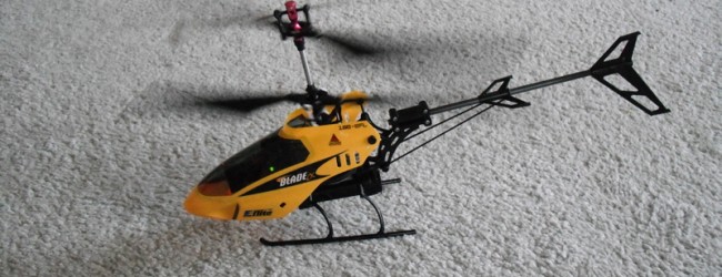
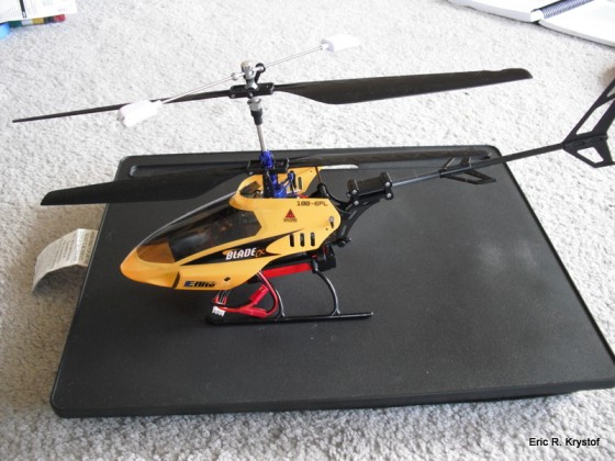
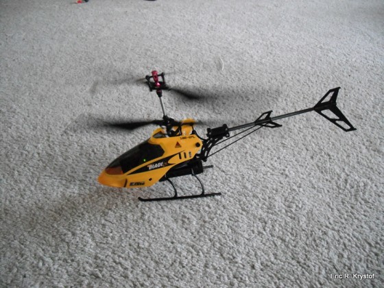
First off, let’s look at what my CX3 looks like now, because it certainly isn’t stock. We’ve an aluminium (okay, I use the spelling with an i) swash plate and a boom kit from Boomtown Hobbies. I’ve also upgraded the skids to a more flexible rubber version. Oh yes, and the canopy…not so much a CX3 canopy anymore.
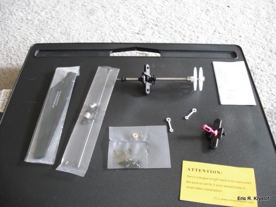
Regardless, the same principles apply. The core upgrade looks like this:
We have replacement shafts, a new flybar, new blades, screws, washers, and bearings.
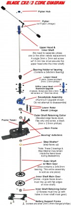
So now, we need to strip down our CX3. The process is quite simple once you’ve done it the first time, for an excellent…or should I say, EXTREMEly excellent reference, look at this forum post on Helifreak. For posterity’s sake, I’ve captured the excellent diagram created by Helifreak User Patriot Front and have posted it here. I post it here because it would be a terrible shame for this to ever be lost.
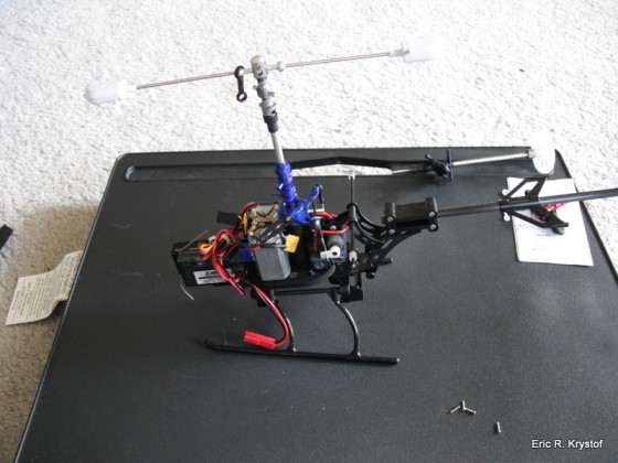
Now, where do we start? I’ve taken the blades off by unscrewing the small screws holding each blade to it’s respective shaft. If you’ve ever replaced blades on the CX, this is a familiar picture.
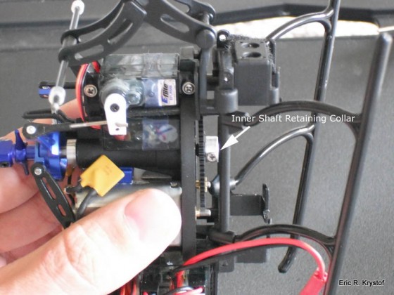
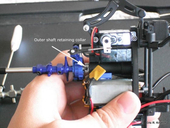
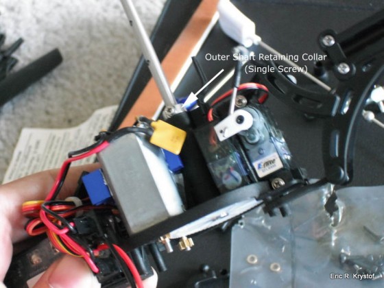
After this point, I remove the inner shaft retaining collar underneath the frame. (You’ll probably need to remove your skids and battery holder that screws into the frame, put them aside for now). The two screws on this collar are usually secured with loc-tite, an easy way to loosen them up is to take the tip of a soldering iron and holding it against the screw for a second to loosen them up. We’ll also remove the single screw from the outer shaft retaining collar that sits right above the frame and the outer shaft.
After the inner shaft retaining collar is loosened and removed, you can remove the inner shaft gear as well as the upper shaft itself by pulling them out of the frame (they can be snug, be careful).
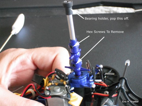
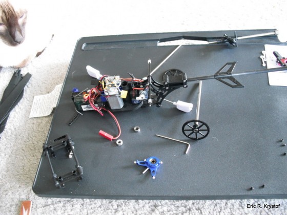
You can see now that my inner-shaft has been removed. (Wrong kind, Mr. Roundtree). We need to next remove the lower rotor blade holder. Either stock plastic or aluminium versions are the same, there are four hex screws that need to be removed.
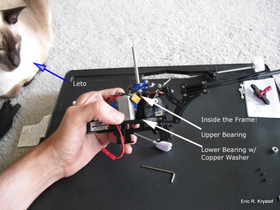
With those removed, I’m left with the swash plate and a loosened retaining collar surrounding the main shaft. If you haven’t yet, snap off the servo rods from the swashplate and slide it off the shaft, followed by the retaining collar. The main shaft should slide right out. Be careful though, there are two bearings (and a copper washer on the bottom one) that are inside the frame. If you want to leave those in, that’s fine, they may or may not come out. The kit comes with two replacement bearings either way. Just make note that you should keep track of the copper washer as the kit comes with one, but we only want to use one of them. In essence, either keep the stock bearings and washer or use the kit bearings and washer, but not both. That’s too much washing and you know what happens (i.e. see EXTREME A-L-L).
Shaft removed, bearings out.
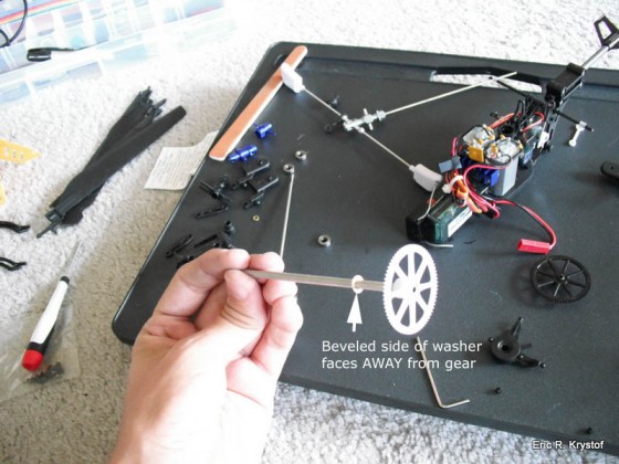
Now we take our new outer shaft and place the new washer on it, beveled side ‘up’ away from the gear.
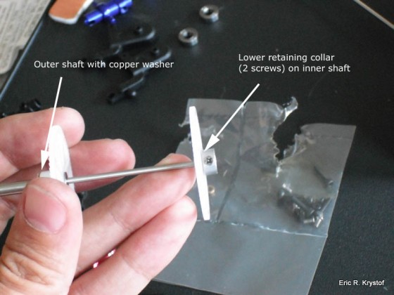
Decision time for you: you can either secure the top pink upper head to the inner shaft or secure the lower retaining collar on the inner shaft first, the choice is yours. I personally attach the lower retaining collar (the kit comes with one, if not use your stock collar) first, since the screws are quite a pain to work with once the shaft is inside the frame. The general setup will look like this:
Put the inner shaft down for now. IF you removed your frame bearings (or they came out), put one bearing onto the outer shaft (sits on top of the washer) and insert the shaft through the bottom of the frame. Slide the other bearing back on so we now have our two bearings inside the frame on our outer shaft. Now, my kit did NOT come with an outer shaft retaining collar, so I used the one taken off earlier. (It’s the retaining collar with only one screw). Slide the retaining collar on the shaft (the collar has a slight bevel to it on one side, you want that beveled side facing the frame/bearing) and secure it tightly. There should be no play on the shaft here, so push the gear in on the frame and make sure your outer shaft retaining collar is down as far is it will go.
Next, slide your swash plate back on to the shaft (I went back to my stock one for weight purposes, so it’s not the blue swash plate anymore), followed by the lower rotor head assembly from the kit (use the kit diagram for orientation if the picture isn’t clear). You don’t have to secure it yet, this is just the order. Then, take the upper bearing holder where the top of the inner shaft meats the outer shaft and put that back on. In essence, we’re reversing our dis-assembly with the kit parts.
Place the inner shaft through the bottom of the frame, it should poke out of the top a little bit, this is where we’ll attach our pink metal hub and secure it with the hex screw provided. You should apply a little force (not too much, bent shafts are not our goal here) so that there is once again no play in the inner shaft as well. Once the pink hub is tightened down, you should be able to pull it away and feel no play at all, same goes for the outer shaft. If there’s play, unscrew and re-tighten.
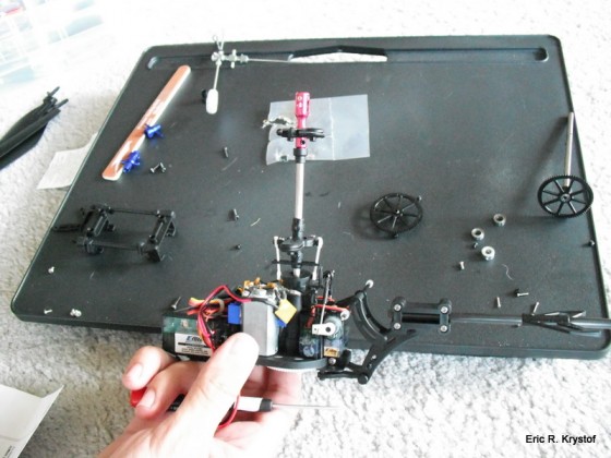
Sounds like a lot, but it’s really just all reversal, and it looks like this.
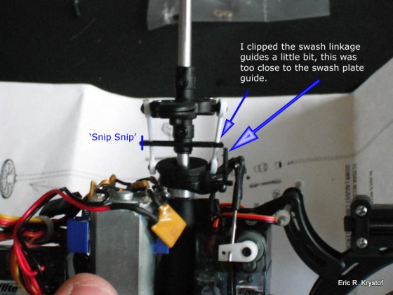
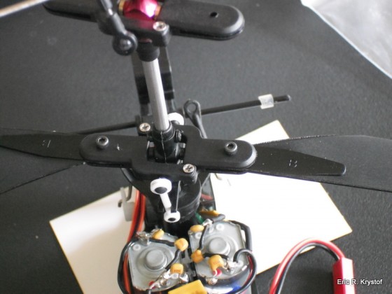
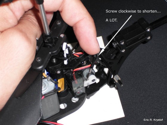
Now that the shafts are nice and secured, let’s start screwing things together. The lower rotor hub is secured to the outer shaft via four screw holes. Use the kit’s small black screws for these. Now, here’s something I noticed while I secured it: The small plastic forks that come out of the lower rotor hub (guides for the swash plate linkage) come EXTREMEly close to the frame guide for the swash plate. I don’t know if this is intentional or not, but it bothered me a bit. It also became rapidly apparent that I was going to have to decrease the link of the servo rods A LOT compared to the stock configuration. It made me a bit uneasy while I was putting this all back together. So uneasy that I actually clipped the forks a few millimeters because I could actually make them connect with the frame otherwise. This is not a game of ‘spinning things meet stationary things without bearings’ I want to play.
You’ll notice in that picture I’ve already assembled and attached the blade grips themselves using the silver screws provided in the kit (remember, small black screws for the shaft, not-as-small silver screws for the blade grips). They easily connect with each other just as your stock blades did.
So now we have everything attached, except for blades and the flybar. Everything else should be screwed in and secured, the only exception is the swash plate, let it just rest on the shaft for now, we’ll get to the servo rods later.
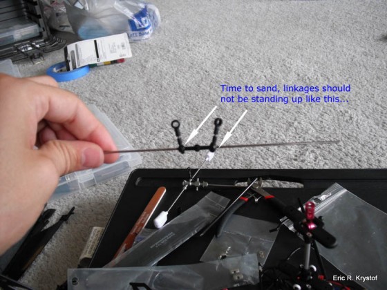
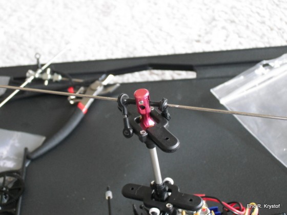
The flybar has two linkages where the stock setup only has one. You may need to remove the linkages and sand the balls so the linkages still fit, but swing a bit more freely. If a linkage attaches to the flybar and doesn’t move freely or drop down by gravity, you’ll need to sand some as I did.
If, after final assembly, your flybar doesn’t swing up and down freely, you may need to sand the balls on the pink metal rotor head as well (where the flybar connects to.
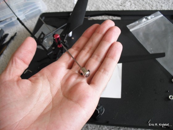
The flybar comes with weights that we need to attach. Two hex screws on opposite sides of each weight secure it. You want the weights to be equidistant, so insert the flybar to the tip of the weight the same length for each side (then measure accordingly if you’d like, the point is that we don’t want to be out of balance).
Now, the blades. ‘B’ for bottom, and ‘A’ for… top. Slide them into the blade grips and tighten with the longer black hex screws. Make sure the blades are tight, they should not be loose, in fact they should only swivel in the blade grips when you apply pressure to them.
Now, the last thing to be secured is the swash plate. However, on my kit the lower rotor head sits so low, I can’t level the swash plate without REALLY shortening the length of the servo rods… Okay, I’ll bite.
Now, for swash plate leveling, I use an eyeball method and then adjust after some flight practice. While eyeballing the swash plate, it helps to actually hook up the battery and transmitter to the aircraft. Disconnect the throttle plug from your receiver and supply power to your unit. The reason we’re doing this is to give some power to the servos, which will naturally keep neutral position when supplied with power.
Screwing in both servo rods, you should be able to then connect them to the swash plate and rotate through the servo motions with your transmitter. (You did disconnect throttle, RIGHT?) You can generally eyeball the level of the swash plate when the servos are in neutral position (i.e. not touching the sticks), it should be nice and flat, perpendicular to the shaft.
Now, if, after flying, you’re noticing the helicopter wants to move a specific direction on it’s own, you’ll need to land, shorten or lengthen a servo rod, and try again. You can tell which servo controls which motion (back/forward or left/right) by using your transmitter and watching which rod servo rod moves when you apply back/forward or left/right motion on the cyclic.
This can take a bit of time, and I actually used some trimming on my transmitter to help out a bit.
You also can secure any shaft screws with loc-tite, just as the stock configuration was on my inner shaft retaining collar on the bottom of the frame. I personally don’t secure them with loctite myself until I’m good and sure it flies well and there’s no complete dis-assembly required.
Attaching my battery holder and skids….and voila… Done!
So, there you have it. After a test flight I noticed my CX3 flies quite well, better than I’ve had it flying, in fact. The servo push rod shortening worried me a little bit in the beginning, but it worked out with some transmitter trim. Is this upgrade EXTREMEly vital? I could argue either way, though I do love the durability of the blades. Was it fun to tinker? Always ![]()

