Date posted: August 5, 2010
- Types of LEDS and Power Sources
- LED Characteristics and The Simple LED Circuit
- More Series LED Circuits
- Parallel LED Circuits
- LED Circuit Tools and LED Strip Kits
- Wiring Standard Bulb LEDs
- SMD LED Circuit Wiring
- LED Wiring and Current Check for Battery Power
- Placing your LED circuits on your RC Craft
- Remote Controlling your LED Circuit
- Painting With Flight
– Download LED Circuit Tools and LED Strip Kits as PDF –
If you’re building your own circuits, chances are you’ll need a lot of these tools or equivalents. If you’re not, well, then skip down to our Strip LED section. I still urge you, however, to take a gander, as you’ll need some of these tools if you’re extending wires to those strip kits.
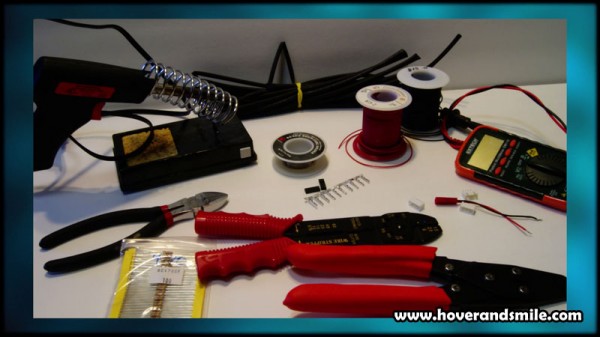
Tools of the circuit building trade
Last time, we finished up some of our theoretical look at simple direct current LEDcircuits. We covered resistors in a circuit, limiting current, and using calculators to do all the mathematical framework for you. We covered series circuits and parallel circuits.
Here’s a quick rundown of the tools we use in building our LED circuits and some places to look for purchasing them. Many can be from local electronics/hardware shops, while you can always search online for whatever site currently holds the best deal for you.
- Soldering Gun/Iron – Wiring circuits requires solder. Think of it as hot metal glue. Pick up a 30-40 watt soldering iron, preferably with a nice pointed tip for handling the small electronic soldering points we’ll be dealing with. I purchased this one from Lowe’s, but virtually any hobby/hardware store has a soldering gun. The holder is a cheap one from Radio Shack, but note the yellow sponge. Get one of those, or a cloth, to keep wet and clean your soldering iron between uses.
- Solder – Iron gets hot, touches solder. Solder melts, touches wires. Wires get ‘tinned’ and are ready to be touched to other wires, soldering gun melts the solder on the wires together, and voila – your wires are connected. I use lead free rosin core solder, a typical type of solder for electronics hobby soldering.
- Wire – I’m using 26 AWG wire here. The lower the gauge, the thicker the wire. It’s backwards, but it’s true. You can get thinner wire than this, called Magnet wire, which is a thin strand of wire coated with an enamel insulation. Either way, you need wire to connect your circuits, but the thicker wire can handle more current. If you’re using simple circuits that pull less than an amp, the 26 AWGwire will probably work. Magnet wire, since it’s so thin, is generally used for a hundred or so milliamps of current or less. Thinner wire is easier to ‘hide’, but can’t handle a lot of LEDs. Radio shack is a quick fix for this type of wire, otherwise you can check out places such as Amazon, eBay, or distributors such as Unicorn Electronics
- Shrink Tube – Shrink Tube is a thin rubber like tube that fits over wires. Upon heating, either with a heat gun or a quick run over a lit flame, the tube shrinks permanently over an object. A great way to protect wires you’ve soldered together from both short circuits or the elements. I’ve purchased some onlinehere in the past, a bulk order that has kept me going all year. Otherwise, once again, Amazon has references for it, as well as your local hobby shop.
- Multimeter – Your basic electronics friend. You can measure voltage of a battery, current through a circuit, even the resistance of an unknown resistor (or if you don’t feel like looking up the little color codes on them). This and a Watt-Meter are invaluable for any of the work I’ve done with RC electronics over the year. Available at local hobby and hardware shops, I’m sure you can search for more snazzy ones online. Some even have oscilloscopes built in!
- Connectors – You’ll need to know your battery and find the opposite end connector for it. Your favorite RC websites typically have the opposite ends, especially for those interested in wiring series/parallel battery circuits or wiring their own Li-Po packs together. I bought a couple of bags of 2 cell, 3 cell and 4 cell ‘female ends’ from Digikey to tap into the balancing jack on my Li-Po battery. If you use your own battery for LED circuits or your flight pack battery, you’ll need connectors!
If you tap into the balancing port on your pack – you’ll need to buy the opposite female versions of your balancing plug to insure you can ‘plug in’ your lights for lighting, then remove it so you can still use the balancing plug on your battery for charging. You’re looking for either the plugs alone ( examples – packs from Digikey for3S Lipos and 2S Lipos ) or balancing cables that you can just cut ends off like here atRC Dude Hobbies , just match your battery’s balancing plug type. As far as which wires to use – use the two wires on the far end of your balancing plug. This will give you the full voltage of your Li-Po pack, whereas the center wires from the balancing plug are best left for the balancing charger to access individual cells.
- Wire cutters / Crimping Tools / Wire Strippers – All very useful tools for removing insulation from wire for soldering, cutting wire down to size, or crimping the small metal crimps onto the ends of wires, just like you’ll see if you look at a servo connector. You may get away without any of the crimping pins if you buy connectors that are pre-wired.
- Resistors – We’ve covered what they do – they limit current. However, if you buy too many from Radio Shack, it can be a bit costly. Look atwww.unicornelectronics.com or The Electronic Goldmine if you want to buy bulk and save.
Strip LED sizing
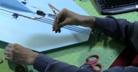
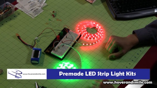
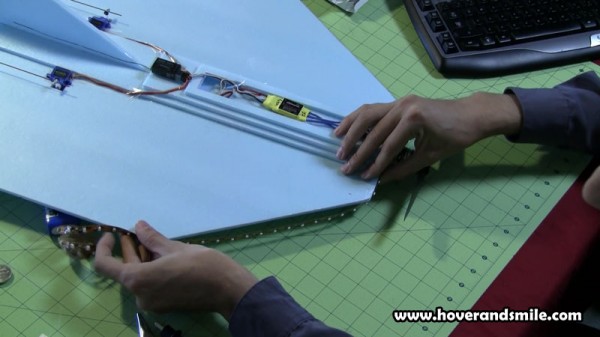
The Strip LEDs don’t require much of that knowledge, just give them juice and they light up. You can see I’ve wired them up to a breadboard (though you could go direct to the battery, breadboards have a high geek factor and make testing circuits easy) and the red and green strips are lit up. But how long to make these strips? I don’t want to use the whole thing, so let’s just roughly place it on the delta wing and measure out:
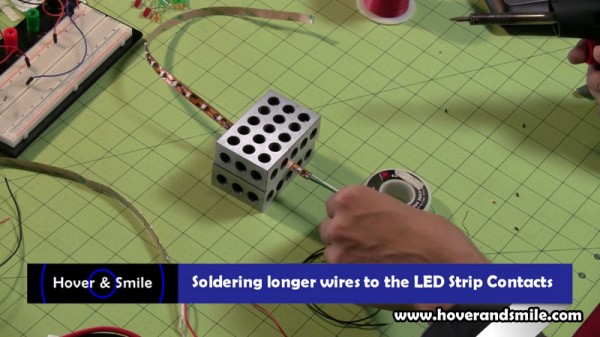
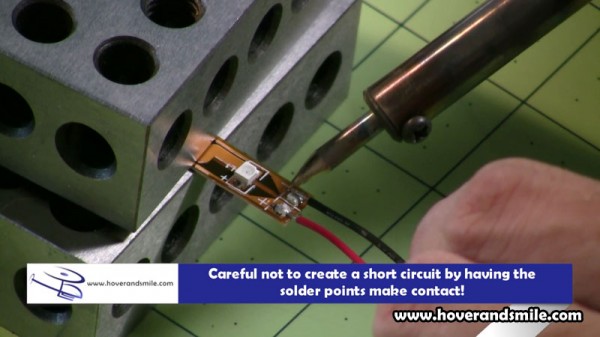
If you look at the LED Strips up close, every three LEDs there is a break point. You can cut this break point and still use both ‘sides’ of the strip at the cut. Just solder up some wires to the marked + and – signs and you’re good to go. Since we are using just part of our strip and we need longer wires to go down our fuselage, we’ll remove the small wires that came with the strip and add our own.
With a heated solder gun, simply melt the solder against the wires and lift them up. You may need to re-tin the contact circle on the strip LEDs by placing some fresh solder on the small contact circles.
Here we’re adding wires of the length we want to the circuit, and after those wires are attached you can simply test them with your circuit by connecting the positive wire to the positive end of your battery, and the negative to the negative.
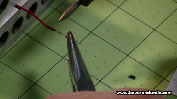
Now, for our green strip specfically, I wanted to add a small resistor to reduce the brightness just a tad, as the red LED strip isn’t as bright. Taking a 33 Ohm resistor, we also tin (tinning is the process of adding solder to a wire or connection point) the resistor, using either a wiring jig or a pair of pliers. Try not to keep heat on too long, just enough to melt solder on the tips.
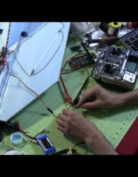
We tin our wires, and the resistor, and then place them against each other, using the soldering iron to melt the solder on both ends and fuse the connection together.
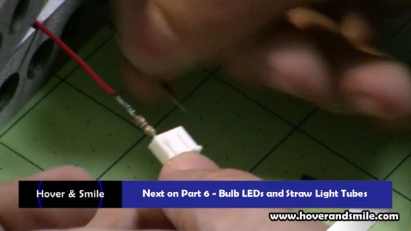
Now, the shrink tube is useful here to cover up that resistor. We can easily test our slightly dimmed circuit, this time by using the outside wires of a Li-Po balancing jack, making sure once again, matching positive and negative (positive is typically red, negative is typically black).
In the next part, we’ll go over how we’ll solder our bulb LEDs for our spotlight and straw light tube.

