Date posted: July 24, 2009
– Download Enclosed LED Circuit, Mark I as PDF –
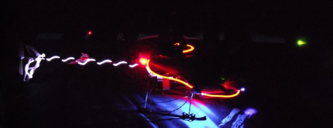
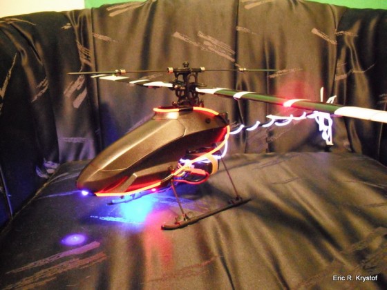
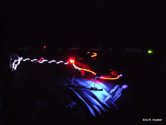
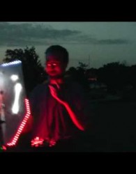
Completing my Night Flying setup, First Round. A simple circuit with three canopy LEDs and enclosure, tapping into the balance lead. Also includes the LED blades and light strings.
Continuing on my fascination with customizing helicopters over actually _flying_ them, I wanted to put together my first complete (for my tastes) Night Flying rig. It’s a Blade CPP Pro 2 with the following customizations:
- EL Light Strings – Purchased at my LHS (HobbyTown USA, Irvington Exit, Omaha, NE). They have a driver which plugs directly into the receiver, each driver supports two strings.
- LED Blades – See how I made them here.
- Simple 12 V LED Circuit - Tapping into the balancing lead on the battery allows me to light the LEDS without needing to tap into the receiver or supply an auxiliary power source (although either would work).
This article is called Mark I for a reason. This is a first attempt at making sure I wired the balancing lead plug properly (not that it’s difficult, but we have to start somewhere), and create a simple wire circuit that is completely embedded in the enclosure.
That being said, future versions will be a bit more modular, allowing different LEDs to plug into the enclosure without being fixed inside (i.e. more plugs), as well as 3 cell and 2 cell hookups. Over time, with a little bit of luck, I also plan on possibly including components such as:
- 555 Timer chip – Time to learn how to make these things properly blink!
- TinyAVR Microcontroller – Adding some interesting logic to the LED lighting
- Voltage Regulator – Keeping some constant voltage without having to worry about the battery’s eventual drain while flying.
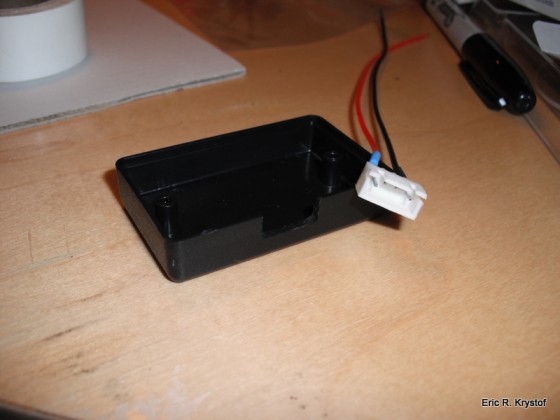
I ordered some female JST plugs with attached wires. This will be the female counterpart to the already existing male balancing plug on my 3 cell li-po. Tapping into all three cells is what I’m looking for, so I leave the ground (black wire) connected and pull out the middle two wires, leaving only the two pairs for power:
The plastic case was a small selection I ordered from Polycase to give the wiring some protection. The case and lid form a solid box, so I had to use the Dremel to cut out enough space for the plug:
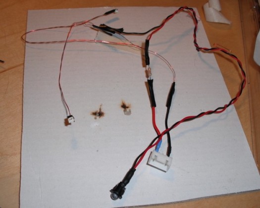
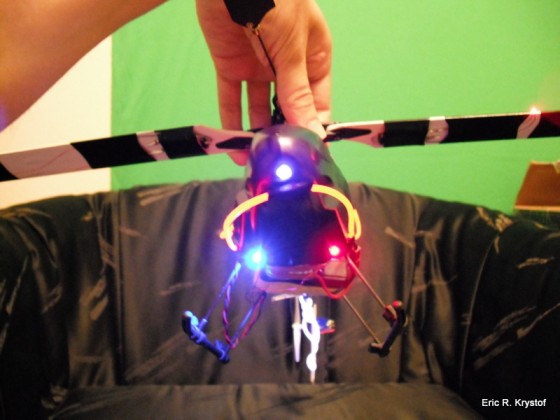
Now, the general idea was to have three LEDs – One LED for the center of the canopy nose, and two LEDs for the canopy body mid-section. I attached some wire to a UV LED from Radio shack, and as far as the other two LEDs, my article on LED blades shows how I soldered the other two SMD LEDs.
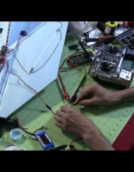
Our circuit is three LEDs in series and a 330 Ohm Resistor. Taking each of the wires and soldering positive to negative to positive to negative, etc, until the circuit is formed.
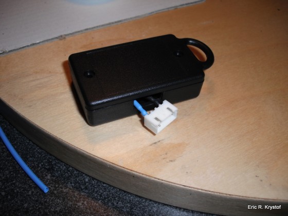
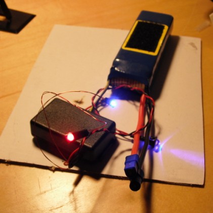
After using the Dremel to cut a small hole into the enclosure for the wires to come outward, the enclosure looks like this with an example 3 cell lipo connected:
I’ve never really needed to use my Dremel more than a few times before I started this hobby. Now it’s right next to my soldering iron as the cool tool of choice.
Taking a Dremel bit and drilling out three openings in the canopy, I fed the wires coming from the enclosure and electrical taped the wires down. This is one of the drawbacks for the Mark I design – the wires are attached to the canopy, and they’re attached to the enclosure. Next time I’ll look at making plug in areas per LED, so if an LED dies or I get bored with a color, I can just unplug the LED from the enclosure instead of being forced to open up the enclosure.
Once the canopy is on, however, with all three night flying components combined, I think my CPP2 is looking pretty good and set for a nice little night flight.
Tags: canopies, helis, LED, night flying, SMD
