Date posted: August 7, 2010
- Types of LEDS and Power Sources
- LED Characteristics and The Simple LED Circuit
- More Series LED Circuits
- Parallel LED Circuits
- LED Circuit Tools and LED Strip Kits
- Wiring Standard Bulb LEDs
- SMD LED Circuit Wiring
- LED Wiring and Current Check for Battery Power
- Placing your LED circuits on your RC Craft
- Remote Controlling your LED Circuit
- Painting With Flight
– Download Wiring Standard Bulb LEDs as PDF –
We’ll use 3 White LEDs from Radio Shack, wired in series. Two pairs of this circuit will be created, one for each side of the craft. One of the LEDs points to the rudder, and the other two will be placed at opposite ends of a straw to make a ‘tube of light’ on the top side of our Combat! flyer.
Your standard Bulb LED
To calculate the resistor values you’ll need, you can reference our earlier articles on how to do that manually, or just use one of these handy little web resistance calculators:
Since in our example we have 12.6 volts from our 3S battery (that’s the maximum of course – the battery will have less voltage over time as we discharge it). Our Radio Shack LED package says that the lights have a mcd rating of 7000 (bright!), have a forward voltage of 3.6 volts, and require a current of 20 milliamps (.02 amps).
So, plugging that into our calculator, we get 100 ohms as our resistance value required to wire up all three LEDs in series for our example power supply.
I don’t have a 100 Ohm resistor, but I can use the next highest number that I do have, which is 110 Ohms.
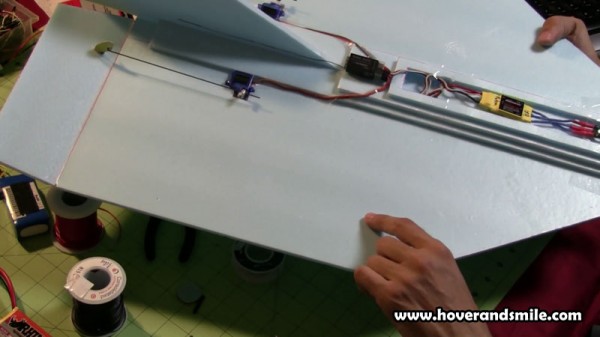
Now that we have the parts we need, take one last look at our naked top side of our flyer as we mentally measure out the wire lengths for our craft.
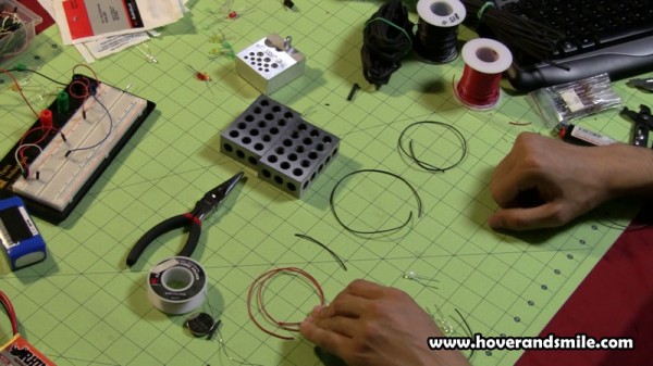
We’ll use one length of red wire to help us remember the positive end, and the rest will be black.
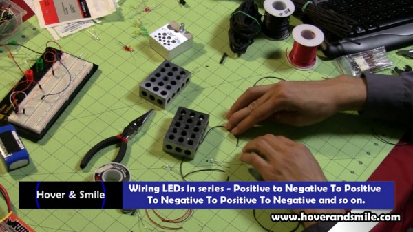
As for the wiring order, look at the wiring diagram from the LED wizard. You can see that the LEDs are wired from positive to negative all the way down the line. So the negative lead from the first LED will connect to the positive lead of the second LED, and so on.
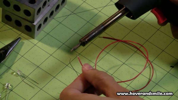
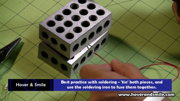
As we strip insulation from the wire ends, we’ll need to ‘tin’ our wires and LEDs with some solder by quickly and simply heating the wire with the soldering iron and letting solder flow onto the wire tip.
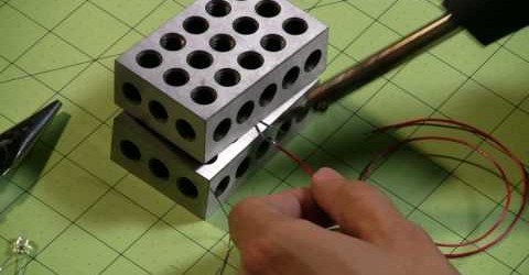
Soldering the LED to the wire is simply a matter of connecting the two pieces and heating the tinned elements with the soldering iron.
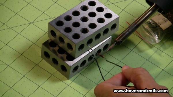
At the end of the wiring line, just before the last wire, we’ll go ahead and solder our tinned resistor:
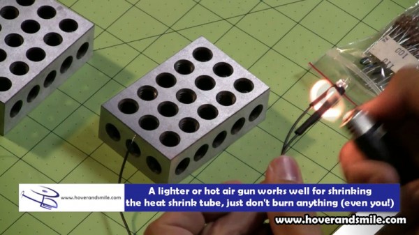
Now, a great way to protect your circuit is to have some shrink tube, or electrical tape, anything to wrap around the wires and keep them from short circuiting, as well as protecting the elements. I prefer the shrink tube method here, so we’ve cut small pieces and slid them over the wires as we wired up our circuit.
Then, with a simple flame or heat gun, heat the shrink tube to condense it over our circuit. Just be careful with the flame, don’t burn the electronics, wires, or yourself!
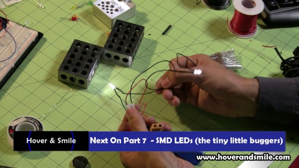
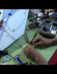
Finally, our circuit is complete, and we can test it by taking the positive and negative ends and attaching them to our battery. In the next article, we’ll go over a little bit more difficult LED handling – SMD LEDs, the tiny strip LEDs you can also buy individually and wire your own circuits up with. Fun, but tiny!

